RS-232 & RS-485
When FPGAs communicate with external devices over UART, the signal rarely stays at 3.3V CMOS all the way to the destination. RS-232 defines an electrical standard for single-ended serial links up to 15 m, while RS-485 uses differential signaling to reach 1,200 m on a multi-drop bus. The most important lesson of this episode: UART is a logical protocol, and RS-232/RS-485 are completely separate physical standards that FPGA GPIO cannot directly drive.
UART vs RS-232 vs RS-485
UART = Logical protocol (3.3V/0V digital signal) RS-232 / RS-485 = Physical electrical standards (RS = Recommended Standard)
┌──────────┐   UART logic    ┌────────────┐  RS-232/485 signal  ┌──────────┐
│   FPGA   ├────────────────►│ Transceiver├────────────────────►│  Device  │
│  (3.3V)  │  TX/RX (CMOS)   │ (MAX3232 / │  (±15V / ±5V diff)  │          │
└──────────┘                 │  RS485)    │                     └──────────┘
                             └────────────┘
- FPGA outputs 3.3V CMOS UART signals
- A transceiver IC converts the signal for long-distance transmission
RS-232 vs RS-485 Comparison
| Item | RS-232 | RS-485 |
|---|---|---|
| Signal Type | Single-ended (referenced to GND) | Differential (A and B wires) |
| Logic Levels | 1 = −3V to −15V, 0 = +3V to +15V | A−B > +200mV = 0, A−B < −200mV = 1 |
| Max Distance | Up to 15 m | Up to 1,200 m |
| Max Speed | 115.2 kbps typical, ~1 Mbps (short range) | 10 Mbps (short range) |
| Multi-drop | Not supported (1:1 only) | Up to 32 nodes (1:N) |
| Duplex | Full-duplex (TX, RX, GND) | Half-duplex (2-wire A/B) |
| Connector | DB-9 (9-pin) | Terminal block, RJ45 |
RS-232 Details
Electrical Characteristics
Logic '1' (MARK)  : −3V to −15V  ← Negative voltage = logic 1 !
Logic '0' (SPACE) : +3V to +15V  ← Positive voltage = logic 0 !
Opposite polarity from TTL/CMOS — a transceiver is always required.
Warning: RS-232 voltages (up to ±15V) will damage FPGA I/O pins rated for 3.3V. Never connect an RS-232 cable directly to FPGA GPIO without a MAX3232 or equivalent transceiver. The transceiver also performs the polarity inversion automatically — the FPGA side sees standard TTL levels.
RS-232 Signal on Oscilloscope
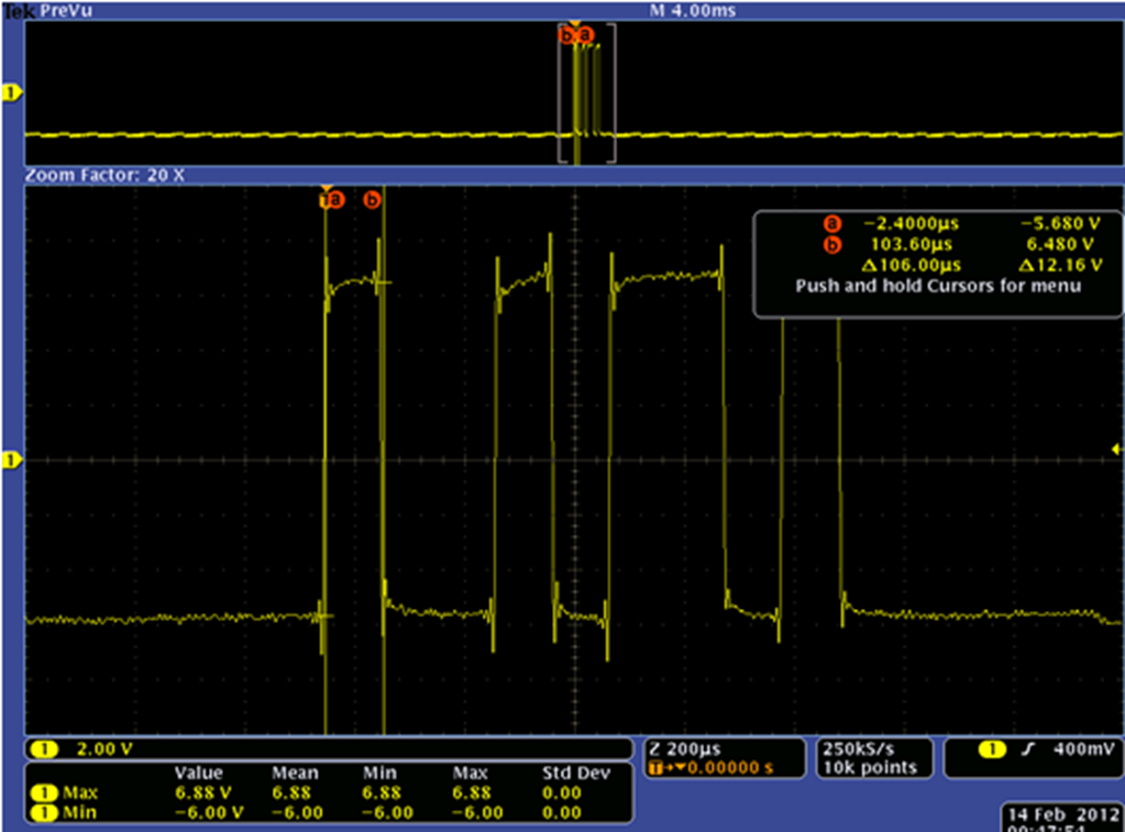
RS-232 UART Oscilloscope Screenshot by Haji Akhundov, licensed under CC BY-SA 3.0
Representative Transceiver: MAX3232 (TI)
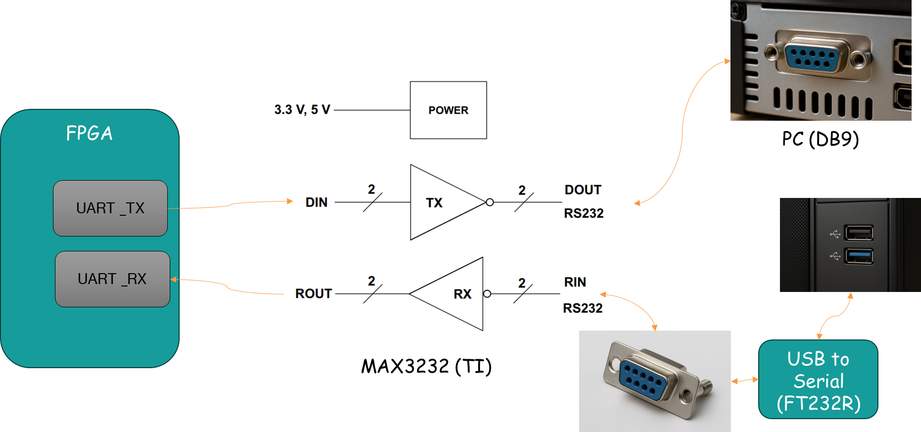
- Operates at 3.3V (internal charge pump generates ±5.5V)
- USB-UART bridge (FT232R, CP2102) can replace RS-232 for PC connection
RS-485 Details
Differential Signal Principle
- Data is determined by the voltage difference (A−B)
- Noise is injected equally into both A and B → cancels out in the difference (CMRR)
Wiring Options
- 2-wire: A, B half-duplex — requires DE/RE direction control
- 4-wire: TX+/TX−, RX+/RX− full-duplex
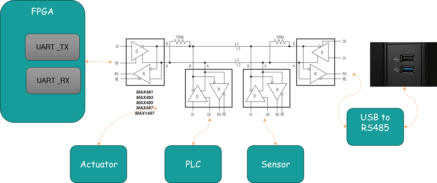
RS-485 Bus Topology
- 120Ω termination resistors: prevent signal reflections; placed at both ends
- Address-based protocols (e.g., Modbus RTU, DMX512) used with RS-485
- DE/RE control: half-duplex requires direction switching
USB-to-UART Bridge
Modern PCs no longer have RS-232 ports → use a USB-UART bridge IC
Common ICs
| IC | Manufacturer | Notes |
|---|---|---|
| FT232R | FTDI | Most widely used, stable drivers |
| CP2102 | Silicon Labs | Compact, USB bus-powered |
| CH340G | WCH | Low-cost, common on Chinese boards |
| PL2303 | Prolific | Legacy, some compatibility issues |
PC USB ──► FT232R ──► UART TX/RX ──► FPGA / MCU
Practical recommendation: For any new UART-to-PC connection, use a USB-UART bridge (FT232R or CP2102) rather than RS-232. Modern laptops have no RS-232 port; the bridge provides a clean 3.3V UART interface, draws power from USB, and installs standard CDC drivers automatically. FT232R has the most stable driver history; avoid PL2303 for new designs.
Practical Summary
RS-232 Connection (FPGA ↔ PC)
FPGA 3.3V UART → MAX3232 → DB-9 (RS-232) → PC (or use USB-UART adapter)
RS-485 Connection (FPGA ↔ Multiple Devices)
FPGA UART → RS-485 driver → A/B bus → each node
                            ← 120Ω termination at each end ←
Practical Tips
- RS-232: best for simple 1:1 debugging (USB-UART bridge preferred today)
- RS-485: ideal for factory floors, meters, elevators and long-distance comms
- Most FPGA boards have a built-in USB-UART bridge (FT232, CP2102)
Episode 3 Summary
- UART = logical protocol; RS-232/485 = physical electrical standard
- RS-232: single-ended, ±15V, max 15 m, 1:1 only
- RS-485: differential, ±5V, max 1,200 m, up to 32 nodes
- Differential signaling: common-mode noise is cancelled (CMRR)
- Practical choice: USB-UART bridge (FT232, CP2102) for PC connection
Next Episode
Episode 4: UART Implementation Methods on FPGA Vendor IP, Soft Processor, and Custom RTL — which one to choose?
Key Takeaways
- UART is a logical protocol (TTL/CMOS levels); RS-232 and RS-485 are physical electrical standards — a transceiver IC is always required between FPGA GPIO and the cable
- RS-232 uses inverted polarity: mark = negative voltage, space = positive — direct connection at ±15V will damage FPGA I/O; always use a MAX3232 or equivalent
- RS-485 differential signaling (A−B voltage) cancels common-mode noise (CMRR), enabling 1,200 m cable runs and 32-node multi-drop buses
- For PC-to-FPGA debug connections, skip RS-232 entirely — use a USB-UART bridge (FT232R or CP2102) for a direct 3.3V UART interface
Code and References
- RTL source repository: https://github.com/Easy-FPGA/easyfpga-uart-core-sv.git
- YouTube: https://www.youtube.com/@easy-fpga